1043.075 DESIGN CRITERIA FOR STORMWATER MANAGEMENT AND DRAINAGE FACILITIES
(a) General Design Guidelines
(a)(1) Stormwater shall not be transferred from one watershed to another, unless:
(a)(1)(A) The watersheds are sub-watersheds of a common watershed which join together within the perimeter of the property;
(a)(1)(B) The effect of the transfer does not alter the peak rate discharge onto adjacent lands; or
(a)(1)(C) Easements from the affected landowner(s) are provided.
(a)(2) Consideration shall be given to the relationship of the subject property to the drainage pattern of the watershed. A concentrated discharge of stormwater to an adjacent property shall be within an existing watercourse or confined in an easement or returned to a pre-development flow type condition.
(a)(3) Innovative stormwater BMP’s and recharge facilities are encouraged (e.g., rooftop storage, drywells, cisterns, recreation area ponding, diversion structures, porous pavements, holding tanks, infiltration systems, in-line storage in storm sewers, and grading patterns). They shall be located, designed, and constructed in accordance with the latest technical guidance published by PADEP, provided they are accompanied by detailed engineering plans and performance capabilities and supporting site specific soils, geology, runoff and groundwater and infiltration rate data to verify proposed designs. Additional guidance from other sources may be accepted at the discretion of the Township Engineer (a pre-application meeting is suggested).
(a)(4) All existing and natural watercourses, channels, drainage systems, and areas of surface water concentration shall be maintained in their existing condition unless an alteration is approved by the appropriate regulatory agency.
(a)(5) The design of all stormwater management facilities shall incorporate sound engineering principles and practices. The Municipality shall reserve the right to disapprove any design that would result in the continuation or exacerbation of a documented adverse hydrologic or hydraulic condition within the watershed, as identified in the plan.
(a)(6) The design and construction of multiple use stormwater detention facilities are strongly encouraged. In addition to stormwater management, facilities should, where appropriate, allow for recreational uses including ball fields, play areas, picnic grounds, and the like. Consulting with the Municipality, and prior approval are required before design. Provision for permanent wet ponds with stormwater management capabilities may also be appropriate.
(a)(6)(A) Multiple use basins should be constructed so that potentially dangerous conditions are not created.
(a)(6)(B) Water quality basins or recharge basins that are designed for a slow release of water or other extended detention ponds are not permitted for recreational uses, unless the ponded areas are clearly separated and secure.
(a)(7) Should any stormwater management facility require a dam safety permit under PADEP Chapter 105, the facility shall be designed in accordance with Chapter 105 and meet the regulations of Chapter 105 concerning dam safety.
(b) Stormwater Management Facility Design Considerations. All stormwater management facilities shall meet the following design requirements:
(b)(1) No outlet structure from a stormwater management facility, or swale, shall discharge directly onto aa Municipal or state roadway without approval from the Municipality or PennDOT.
(b)(2) The top, or toe, of any slope of stormwater management facilities shall be located a minimum of ten feet from any property line.
(b)(3) The minimum horizontal distance between any stormwater holding facility and a building/structure shall be 25 feet.
(b)(4) Stormwater management facility bottom (or surface of permanent pool) elevations must be greater than adjacent floodplain elevations (FEMA or HEC-RAS analysis). If no floodplain is defined, bottom elevations must be greater than existing ground elevations 50 feet from top of stream bank in the facilities’ vicinity.
(b)(5) Basin outflow culverts discharging into floodplains must account for tailwater. Tailwater corresponding to the 100-year floodplain elevation must be used for all design storms, or the applicant may elect to determine flood elevations of the adjacent watercourse for each design storm. The floodplain is assumed to be 50 feet from top of stream bank in areas where a floodway is not designated, or no other evidence is provided.
(b)(6) The invert of all stormwater management facilities and underground infiltration/storage facilities shall be located a minimum of two feet above the seasonal high groundwater table. The invert of stormwater facilities may be lowered if adequate sub-surface drainage is provided. Flows from underdrains need not be accounted for in volume or rate control calculations.
(b)(7) Whenever possible the side slopes and basin shape shall be amenable to the natural topography. Vertical side slopes and rectangular basins shall be avoided whenever possible.
(b)(8) Exterior slopes of compacted soil shall not exceed 3:1, and may be further reduced if the soil has unstable characteristics.
(b)(9) Interior slopes of the basin shall not exceed 3:1.
(b)(10) Unless specifically designed as a volume control facility, all stormwater management facilities shall have a minimum slope of 2% extending radially out from the principal outlet structure. Facilities designed as water quality/infiltration BMPs may have a bottom slope of zero.
(b)(11) Impervious low-flow channels are not permitted within stormwater management facilities.
(b)(12) Unless specifically designed as a volume control or water quality facility, all stormwater management facilities must empty over a period of time not less than 24 hours, and not more than 72 hours, from the end of the facility’s inflow hydrograph. Infiltration tests performed at the facility locations and proposed basin bottom depths, in accordance with the BMP Manual, must support time-to-empty calculations if infiltration is a factor.
(b)(13) Energy dissipaters and/or level spreaders shall be installed at points where pipes or drainageways discharge to or from basins. Discharges to drainage swales shall be dissipated, or piped, to an acceptable point.
(b)(14)(A) Landscaping and planting specifications must be provided for all stormwater management basins, and be specific for each type of basin.
(b)(14)(B) Minimal maintenance, saturation tolerant vegetation must be provided in basins designed as water quality/infiltration BMPs.
(b)(15) A safety fence may be required, at the discretion of the Municipality, for any stormwater management facility. The fence shall be a minimum of four feet high, and of a material acceptable to the Municipality. A gate with a minimum opening of 10 feet shall be provided for maintenance access.
(b)(16) Principal Outlet Structures. The primary outlet structure shall be designed to pass all design storms (up to and including the 100-year event) without discharging through the emergency spillway. All principal outlet structures shall:
(b)(16)(A) Be constructed of reinforced concrete or an alternative material approved by the Township Engineer. When approved for use, all metal risers shall:
(b)(16)(A)(1) Be suitably coated to prevent corrosion,
(b)(16)(A)(2) Have a concrete base attached with a watertight connection. The base shall be sufficient weight to prevent flotation of the riser,
(b)(16)(A)(3) Provide a trash rack or similar appurtenance to prevent debris from entering the riser,
(b)(16)(A)(4) Provide an anti-vortex device, consisting of a thin vertical plate normal to the basin berm.
(b)(16)(B) Provide trash racks to prevent clogging of primary outflow structure stages for all orifices.
(b)(16)(C) Provide outlet aprons and shall extend to the toe of the basin slope at a minimum.
(b)(17) Emergency Spillways. Any stormwater management facility designed to store runoff shall provide an emergency spillway designed to convey the 100-year post-development peak rate flow with a blocked primary outlet structure. The emergency spillway shall be designed per the following requirements:
(b)(17)(A) The top of embankment elevation shall provide a minimum one foot of freeboard above the maximum water surface elevation. This is to be calculated when the spillway functions for the 100-year post-development inflow, with a blocked outlet structure.
(b)(17)(B) Avoid locating on fill areas, whenever possible.
(b)(17)(C) The spillway shall be armored to prevent erosion during the 100-year post-development flow, with a blocked primary outlet structure.
(b)(17)(C)(1) Synthetic liners or riprap may be used, and calculations sufficient to support proposed armor must be provided. An earthen plug must be used to accurately control the spillway invert if riprap is the proposed armoring material. Emergency spillway armor must extend up the sides of the spillway, and continue at full width to a minimum of ten feet past the toe of slope.
(b)(17)(D) The Municipality may require the use of additional protection when slopes exceed 4:1 and spillway velocities might exceed NRCS standards for the particular soils involved.
(b)(17)(E) Any underground stormwater management facility (pipe storage systems) must have a method to bypass flows higher than the required design (up to a 100-year post-development inflow) without structural failure, or causing downstream harm or safety risks.
(b)(18) Stormwater Management Basins. Design of stormwater management facilities having three feet or more of water depth (measured vertically from the lowest elevation in the facility to the crest of the emergency spillway) shall meet the following additional requirements:
(b)(18)(A) The maximum water depth within any stormwater management facility shall be no greater than eight feet when functioning through the primary outlet structure.
(b)(18)(B) The top of embankment width shall be:
(b)(18)(B)(1) For embankments up to four feet, width shall be at least six feet;
(b)(18)(B)(2) For embankments between four and six feet, width shall be at least eight feet;
(b)(18)(B)(3) For embankments over six feet, width shall be at least ten feet.
(b)(18)(C) A 10-foot wide access to the basin bottom must be provided with a maximum longitudinal slope of 10%.
(b)(18)(D) Berms shall be constructed using soils that conform to the unified soil classification of CH, MH, CL or ML. Soils used shall be tested to determine its density analysis per ASTM 698. The embankments will be constructed in a maximum of six-inch lifts. The lifts will each be compacted to a density at least 98% of the maximum dry density. Each layer of compacted fill shall be tested to determine its density per ASTM 2922 or ASTM 3017. One test per 50 cubic yards of material placed (at least one per layer) shall be performed by an independent testing agency.
(b)(18)(E) A cutoff and key trench of impervious material shall be provided under all embankments four feet or greater in height. The cutoff trench shall run the entire length of the embankment and tie into undisturbed natural ground.
(b)(18)(F) Anti-seep collars, or a PADEP approved alternative, must be provided on all outflow culverts in accordance with the methodology contained in the latest edition of the PADEP E&S Manual. An increase in seepage length of 15% must be used in accordance with the requirements for permanent anti-seep collars.
(b)(19) Construction of Stormwater Management Facilities
(b)(19)(A) Basins used for rate control only shall be installed prior to or concurrent with any earthmoving or land disturbances, which they will serve. The phasing of their construction shall be noted in the narrative and on the plan.
(b)(19)(B) Basins that include water quality or recharge components shall have those components installed in such a manner as to not disturb or diminish their effectiveness.
(b)(19)(C) Compaction test reports shall be kept on file at the site and be subject to review at all times with copies being forwarded to the Township Engineer upon request.
(b)(19)(D) Temporary and permanent grasses or stabilization measures shall be established on the sides and base of all earthen basins within 15 days of construction.
(b)(20) Exceptions to these requirements may be made at the discretion of the Municipality for BMPs that retain or detain water, but are of a much smaller scale than traditional stormwater management facilities.
(c) Stormwater Carrying Facilities
(c)(1) All storm sewer pipes, grass waterways, open channels, swales and other stormwater carrying facilities that service drainage areas within the site must be able to convey post-development runoff from the 10-year design storm.
(c)(2) Stormwater management facilities that convey off-site water through the site shall be designed to convey the 25-year storm even (or larger events, as determined by the Township Engineer).
(c)(3) All developments shall include provisions that allow for the overland conveyance and flow of the post-development 100-year storm event without damage to public or private property.
(d)(4) Storm Sewers
(d)(4)(A) Storm sewers must be able to convey post-development runoff without surcharging inlets for the 10-year storm event.
(d)(4)(B) When connecting to an existing storm sewer system, the applicant must demonstrate that the proposed system will not exacerbate any existing stormwater problems and that adequate downstream capacity exists.
(d)(4)(C) A minimum pipe size of 18 inches in diameter shall be used in all roadway systems (public or private) proposed for construction in the Municipality. Pipes shall be designed to provide a minimum velocity of two and one-half feet per second when flowing full, but in all cases, the slope shall be no less than 0.5%. Arch pipe of equivalent cross-sectional area may be substituted in lieu of circular pipe where cover or utility conflict conditions exist.
(d)(4)(D) All storm sewer pipes shall be laid to a minimum depth of one foot from subgrade to the crown of pipe.
(d)(4)(E) In curbed roadway sections, the maximum encroachment of water on the roadway pavement shall not exceed half of a through travel lane or one inch less than the depth of curb during the 10-year design storm of five minute duration. Gutter depth shall be verified by inlet capture/capacity calculations that account for road slope and opening area.
(d)(4)(E)(1) Inlets shall be placed at a maximum of 400 feet apart.
(d)(4)(E)(2) Inlets shall be placed so drainage cannot cross intersections or street centerlines.
(d)(4)(F) All inlets shall provide a minimum two-inch drop between the lowest inlet pipe invert elevation and the outlet pipe invert elevation.
(d)(4)(G) On curbed sections, a double inlet shall be placed at the low point of sag vertical curves, or an inlet shall be placed on each side of the low point at a distance not to exceed 100 feet, or at an elevation not to exceed 0.2 feet above the low point.
(d)(4)(H) At all roadway low points, swales and easements shall be provided behind the curb or swale and through adjacent properties to channelize and direct any overflow of stormwater runoff away from dwellings and structures.
(d)(4)(I) All inlets in paved areas shall have heavy duty bicycle safe grating. A note to this effect shall be added to the SWM site plan or inlet details therein.
(d)(4)(J) Inlets must be sized to accept the specified pipe sizes without knocking out any of the inlet corners. All pipes entering or exiting inlets shall be cut flush with the inside wall of the inlet. A note to this effect shall be added to the SWM site plan or inlet details therein.
(d)(4)(K) Inlets shall have weep holes covered with geotextile fabric placed at appropriate elevations to completely drain the sub grade prior to placing the base and surface course on roadways.
(d)(4)(L) Inlets, junction boxes, or manholes greater than five feet in depth shall be equipped with ladder rungs and shall be detailed on the SWM site plan.
(d)(4)(M) Inlets shall not have a sump condition in the bottom (unless designed as a water quality BMP or specifically approved by the Municipality). Pipe shall be flush with the bottom of the box or concrete channels shall be poured.
(d)(4)(N) Accessible drainage structures shall be located on continuous storm sewer system at all vertical dislocations, at all locations where a transition in storm sewer pipe sizing is required, at all vertical and horizontal angle points exceeding five degrees, and at all points of convergence of two or more storm sewer pipes.
(d)(4)(O) All storm drainage piping shall be provided with either reinforced concrete headwalls or end sections of compatible material as the pipe involved at its entrance and discharge.
(d)(4)(P) (1) Outlet protection and energy dissipaters shall be provided at all surface discharge points in order to minimize erosion consistent with the E&S Manual.
(d)(4)(P)(2) Flow velocities and volumes from any storm sewer shall not result in a degradation of the receiving channel.
(d)(4)(Q) Stormwater roof drains and pipes shall not be connected to storm sewers or discharge onto impervious areas without approval by the Township Engineer.
(d)(5) Swale Conveyance Facilities
(d)(5)(A) Swales must be able to convey post-development runoff from a ten-year design storm with six inches of freeboard to top of the swale.
(d)(5)(B) Swales shall have side slopes no steeper than 3:1.
(d)(5)(C) All swales shall be designed, labeled on the SWM site plan, and details provided to adequately construct and maintain the design dimension of the swales.
(d)(5)(D) Swales shall be designed for stability using velocity or shear criteria. Velocity criteria may be used for channels with less than 10% slope. Shear criteria may be used for all swales. Documentation must be provided to support velocity and/or shear limitations used in calculations.
(d)(5)(E) Where swale bends occur, the computed velocities or shear stresses shall be multiplied by the following factor for the purpose of designing swale erosion protection:
(d)(5)(E)(1) 1.75 – when swale bend is 30 to 60 degrees.
(d)(5)(E)(2) 2.00 – when swale bend is 60 to 90 degrees.
(d)(5)(E)(3) 2.50 – when swale bends is 90 degrees or greater.
(d)(5)(F) Manning’s “n” values used for swale capacity design must reflect the permanent condition.
1043.076 CALCULATION METHODOLOGY
(a) All calculations shall be consistent with the guidelines set forth in the BMP Manual, as amended herein.
(b) Stormwater runoff from all development sites shall be calculated using either the Rational Method or the NRCS Rainfall-Runoff Methodology. Other methods shall be selected by the design professional based on the individual limitations and suitability of each method for a particular site and approved by the Township Engineer.
(c) Rainfall Values
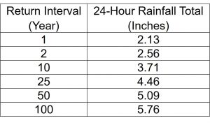
(c)(1) NRCS Rainfall-Runoff Method. The Soil Conservation Service Type II, 24-hour rainfall distribution shall be used in conjunction with rainfall depths from NOAA Atlas 14 or be consistent with the following table:
(d) Runoff Volume
(d)(1) Rational Method. Not to be used to calculate runoff volume.
(d)(2) NRCS Rainfall-Runoff Method. This method shall be used to estimate the change in volume due to regulated activities. Combining curve numbers for land areas proposed for development with curve numbers for areas unaffected by the proposed development into a single weighted curve number is not acceptable.
(e) Peak Flow Rates
(e)(1) Rational Method. This method may be used for design of conveyance facilities only. Extreme caution should be used by the design professional if the watershed has more than one main drainage channel, if the watershed is divided so that hydrologic properties are significantly different in one versus the other, if the time of concentration exceeds 60 minutes, or if stormwater runoff volume is an important factor. The combination of Rational Method hydrographs based on timing shall be prohibited.
(e)(2) NRCS Rainfall-Runoff Method. This method is recommended for design of stormwater management facilities and where stormwater runoff volume must be taken into consideration. The following provides guidance on the model applicability:
(e)(2)(A) NRCS’s TR-20 or HEC-HMS – no size limitations.
(e)(2)(B) Other models as pre-approved by the Municipality. The NRCS antecedent runoff condition II (ARC II, previously AMC II) must be used for all simulations. The use of continuous simulation models that vary the ARC are not permitted for stormwater management purposes.
(e)(3) For comparison of peak flow rates, flows shall be rounded to a tenth of a cubic foot per second (cfs).
(f) Runoff Coefficients
(f)(1) Rational Method. Use Table C-1.
(f)(2) NRCS Rainfall-Runoff Method. Use Table C-2. Curve numbers (CN) should be rounded to tenths for use in hydrologic models as they are a design tool with statistical variability. For large sites, CNs should realistically be rounded to the nearest whole number.
(g) Design Storm
(g)(1) All stormwater management facilities shall be verified by routing the proposed two-year, 10-year, 25-year, and 100-year hydrographs through the facility using the storage indication method or modified puls method. The design storm hydrograph shall be computed using a calculation method that produces a full hydrograph.
(g)(2) The stormwater management and drainage system shall be designed to safely convey the post-development 100-year storm event to stormwater detention facilities, for the purpose of meeting peak rate control.
(h) Time of Concentration
(h)(1) The time of concentration is to represent the average condition that best reflects the hydrologic response of the area. The following time of concentration (Tc) computational methodologies shall be used unless another method is pre-approved by the Township Engineer:
(h(1)(A) Pre-development – NRCS’s Lag Equation:

(h)(1)(B) Post-development; commercial, industrial, or other areas with large impervious areas (>20% impervious area) – NRCS Segmental Method. The length of sheet flow shall be limited to 100 feet. Tc for channel and pipe flow shall be computed using Manning’s equation.
(h)(1)(C) Post-development; residential, cluster, or other low impact designs less than or equal to 20% impervious area – NRCS Lag Equation or NRCS Segmental Method.
(h)(2) Additionally, the following provisions shall apply to calculations for time of concentration:
(h)(2)(A) The post-development Tc shall never be greater than the pre-development Tc for any watershed or sub-watershed. This includes when the designer has specifically used swales to reduce flow velocities. In the event that the designer believes that the post-development Tc is greater, it will still be set by default equal to the pre-development Tc for modeling purposes.:
(h)(2)(B) The minimum Tc for any watershed shall be five minutes.
(h)(2)(C) The designer must provide computations for all pre-development Tc paths. A five minute Tc cannot be assumed for pre-development.
(h)(3)(D) Undetained fringe areas (areas that are not tributary to a stormwater facility but where a reasonable effort has been made to convey runoff from all new impervious coverage to best management practices) may be assumed to represent the pre-development conditions for purpose of Tc calculation.